Calculation of email loads. How to calculate the workload of the HR department. The main types of section calculation
The calculation of the load on the foundation is necessary for the correct choice of its geometric dimensions and the area of the base of the foundation. Ultimately, the strength and durability of the entire building depends on the correct calculation of the foundation. The calculation comes down to determining the load per square meter of soil and comparing it with the allowable values.
To calculate, you need to know:
- The region in which the building is being built;
- Soil type and groundwater depth;
- The material from which the structural elements of the building will be made;
- The layout of the building, the number of storeys, the type of roof.
Based on the required data, the calculation of the foundation or its final verification is carried out after the design of the building.
Let's try to calculate the load on the foundation for a one-story house made of solid solid brick masonry, with a wall thickness of 40 cm. The dimensions of the house are 10x8 meters. The ceiling of the basement is reinforced concrete slabs, the ceiling of the 1st floor is wooden on steel beams. The roof is gable, covered with metal tiles, with a slope of 25 degrees. Region - Moscow region, soil type - wet loams with a porosity coefficient of 0.5. The foundation is made of fine-grained concrete, the wall thickness of the foundation for calculation is equal to the thickness of the wall.
Determining the depth of the foundation
The depth of laying depends on the depth of freezing and the type of soil. The table shows the reference values of the depth of soil freezing in various regions.
Table 1 - Reference data on the depth of soil freezing
Reference table for determining the depth of the foundation by region
The depth of the foundation in the general case should be greater than the freezing depth, but there are exceptions due to the type of soil, they are indicated in table 2.
Table 2 - Dependence of the depth of the foundation on the type of soil

The depth of the foundation is necessary for the subsequent calculation of the load on the soil and determining its size.
We determine the depth of soil freezing according to table 1. For Moscow, it is 140 cm. According to table 2, we find the type of soil - loam. The laying depth must not be less than the estimated freezing depth. Based on this, the depth of the foundation for the house is selected 1.4 meters.
Roof load calculation
The load of the roof is distributed between those sides of the foundation, on which the truss system rests through the walls. For an ordinary gable roof, these are usually two opposite sides of the foundation, for a four-pitched roof, all four sides. The distributed load of the roof is determined by the area of the projection of the roof, referred to the area of the loaded sides of the foundation, and multiplied by the specific gravity of the material.
Table 3 - Specific gravity of different types of roofing
Reference table - Specific gravity of different types of roofing
- We determine the area of the projection of the roof. The dimensions of the house are 10x8 meters, the projection area of the gable roof is equal to the area of the house: 10 8 = 80 m 2.
- The length of the foundation is equal to the sum of its two long sides, since the gable roof rests on two long opposite sides. Therefore, the length of the loaded foundation is defined as 10 2 = 20 m.
- The area of the foundation loaded with a roof with a thickness of 0.4 m: 20 0.4 \u003d 8 m 2.
- The type of coating is metal tiles, the slope angle is 25 degrees, which means that the calculated load according to table 3 is 30 kg / m 2.
- The load of the roof on the foundation is 80/8 30 \u003d 300 kg / m 2.
Snow load calculation
The snow load is transferred to the foundation through the roof and walls, so the same sides of the foundation are loaded as in the calculation of the roof. The area of snow cover is calculated equal to the area of the roof. The resulting value is divided by the area of the loaded sides of the foundation and multiplied by the specific snow load determined from the map.

Table - calculation of snow load on the foundation
- The length of the slope for a roof with a slope of 25 degrees is (8/2) / cos25 ° = 4.4 m.
- The roof area is equal to the length of the ridge multiplied by the length of the slope (4.4 10) 2 \u003d 88 m 2.
- The snow load for the Moscow region on the map is 126 kg / m 2. We multiply it by the area of the roof and divide by the area of the loaded part of the foundation 88 126 / 8 = 1386 kg / m 2.
Floor load calculation
Ceilings, like the roof, usually rest on two opposite sides of the foundation, so the calculation is carried out taking into account the area of \u200b\u200bthese sides. The floor area is equal to the area of the building. To calculate the floor load, you need to take into account the number of floors and the basement floor, that is, the floor of the first floor.
The area of each overlap is multiplied by the specific gravity of the material from table 4 and divided by the area of the loaded part of the foundation.
Table 4 - Specific gravity of floors
- The floor area is equal to the area of \u200b\u200bthe house - 80 m 2. The house has two floors: one of reinforced concrete and one of wood on steel beams.
- We multiply the area of the reinforced concrete floor by the specific gravity from Table 4: 80 500 = 40000 kg.
- We multiply the area of \u200b\u200bthe wooden floor by the specific gravity from table 4: 80 200 \u003d 16000 kg.
- We summarize them and find the load on 1 m 2 of the loaded part of the foundation: (40000 + 16000) / 8 = 7000 kg / m 2.
Wall load calculation
The load of the walls is determined as the volume of the walls, multiplied by the specific gravity from table 5, the result is divided by the length of all sides of the foundation, multiplied by its thickness.
Table 5 - Specific gravity of wall materials

Table - Specific weight of walls
- The wall area is equal to the height of the building multiplied by the perimeter of the house: 3 (10 2 + 8 2) = 108 m 2.
- The volume of the walls is the area multiplied by the thickness, it is equal to 108 0.4 \u003d 43.2 m 3.
- We find the weight of the walls by multiplying the volume by the specific gravity of the material from table 5: 43.2 1800 \u003d 77760 kg.
- The area of all sides of the foundation is equal to the perimeter multiplied by the thickness: (10 2 + 8 2) 0.4 \u003d 14.4 m 2.
- The specific load of the walls on the foundation is 77760/14.4=5400 kg.
Preliminary calculation of the foundation load on the ground
The load of the foundation on the soil is calculated as the product of the volume of the foundation and the specific density of the material from which it is made, divided by 1 m 2 of its base area. The volume can be found as the product of the depth of the foundation and the thickness of the foundation. The thickness of the foundation is taken in the preliminary calculation equal to the thickness of the walls.
Table 6 - Specific density of foundation materials

Table - specific gravity of the soil material
- The foundation area is 14.4 m 2, the laying depth is 1.4 m. The volume of the foundation is 14.4 1.4 \u003d 20.2 m 3.
- The mass of the foundation made of fine-grained concrete is equal to: 20.2 1800 = 36360 kg.
- Ground load: 36360 / 14.4 = 2525 kg / m 2.
Calculation of the total load per 1 m 2 of soil
The results of previous calculations are summarized, and the maximum load on the foundation is calculated, which will be greater for those sides on which the roof rests.
The conditional design soil resistance R 0 is determined according to the tables of SNiP 2.02.01-83 "Foundations of buildings and structures".
- We sum up the weight of the roof, the snow load, the weight of the floors and walls, as well as the foundation on the ground: 300 + 1386 + 7000 + 5400 + 2525 \u003d 16 611 kg / m 2 \u003d 17 t / m 2.
- We determine the conditional design soil resistance according to the tables of SNiP 2.02.01-83. For wet loams with a porosity coefficient of 0.5, R 0 is 2.5 kg/cm 2 or 25 t/m 2 .
It can be seen from the calculation that the load on the ground is within the permissible range.
Determination of maximum loads by the demand factor method
This method is the simplest and comes down to calculating the maximum active load using the formula:
The demand factor method can be used to calculate the loads for those individual groups of power receivers, workshops and enterprises in general, for which there is data on the value of this coefficient (see).
When calculating the loads for individual groups of electrical receivers, this method is recommended to be used for those groups whose electrical receivers operate with a constant load and with a switching coefficient equal to (or close to) unity, such as electric motors of pumps, fans, etc.
According to the value of P30 obtained for each group of power receivers, the reactive load is determined:
![]()
moreover, tanφ is determined by cosφ, characteristic of this group of power receivers.
Then, the active and reactive loads are summed separately and the total load is found:
![]()
The loads ΣР30 and ΣQ30 are the sums of the maximums for individual groups of power receivers, while in fact the maximum of the sum should be determined. Therefore, when determining the loads on a network section with a large number of heterogeneous groups of power receivers, one should introduce the maximum overlap coefficient KΣ, i.e. take:
![]()
The value of KΣ lies in the range from 0.8 to 1, and the lower limit is usually taken when calculating loads throughout the enterprise as a whole.
For high power, as well as for power receivers, rarely or even for the first time encountered in design practice, demand factors should be identified by clarifying the actual load factors together with technologists.
Determination of maximum loads using the two-term expression method
This method was proposed by Eng. D. S. Livshits initially to determine the design loads for electric motors of an individual drive of metal-working machine tools, and then it was extended to other groups of electrical receivers.
According to this method, the half-hour maximum active load for a group of power receivers of the same operating mode is determined from the expression:
![]()
where Run is the installed power of n largest power receivers, b, c-coefficients that are constant for a particular group of power receivers of the same operating mode.
According to the physical meaning, the first member of the calculation formula determines the average power, and the second - the additional power, which can take place within half an hour as a result of the coincidence of the load maxima of individual power receivers of the group. Consequently:


It follows that for small values of Rup compared to Ru, which occurs with a large number of power receivers of more or less the same power, K30 ≈KI, and the second term of the calculation formula can be neglected in such cases, taking P30 ≈ bRp ≈ Rav.cm. On the contrary, with a small number of power receivers, especially if they differ sharply in power, the influence of the second term of the formula becomes very significant.
Calculations by this method are more cumbersome than by the method of demand coefficient. Therefore, the use of the two-term expression method justifies itself only for groups of power receivers operating with variable load and with small switching factors, for which demand factors are either absent at all or can lead to erroneous results. In particular, for example, it is possible to recommend the use of this method for electric motors of metal-working machine tools and for electric resistance furnaces of low power with periodic loading of products.
The methodology for determining the total load S30 using this method is similar to that described for the demand factor method.
Determination of maximum loads by the method of effective number of electrical receivers.
The effective number of power receivers is understood as such a number of receivers, equal in power and homogeneous in mode of operation, which determines the same value of the calculated maximum as a group of receivers of different power and mode of operation.
The effective number of power receivers is determined from the expression:

By size n e and the utilization factor corresponding to this group of power receivers, according to the reference tables, the coefficient of maximum KM is determined and then the half-hour maximum active load
To calculate the load of any one group of power receivers of the same operating mode, the definition of pe makes sense only if the power receivers included in the group differ significantly in power.
With the same power p of electrical receivers included in the group

i.e. the effective number of electric motors is equal to the actual number. Therefore, with the same or slightly different powers of the power receivers of the group, it is recommended to determine the KM by the actual number of power receivers.
When calculating the load for several groups of power receivers, it is necessary to determine the average value of the utilization factor using the formula:

The method of the effective number of power receivers is applicable for any groups of power receivers, including for power receivers of intermittent operation. In the latter case, the installed power Ru is reduced to PV = 100%, i.e., to a long-term operation.
The method of the effective number of power receivers is better than other methods in that the maximum factor, which is a function of the number of power receivers, is involved in determining the load. In other words, this method calculates the maximum sum of the loads of individual groups, and not the sum of the maxima, as is the case, for example, with the demand factor method.
To calculate the reactive component of the load Q30 from the found value of P30, it is necessary to determine tanφ. For this purpose, it is necessary to calculate the average shift loads for each group of power receivers and determine tanφ from the ratio:

Returning to the definition of pe, it should be noted that with a large number of groups and different power of individual power receivers in groups, finding ΣРу2 turns out to be practically unacceptable. Therefore, a simplified method for determining pe is used, depending on the relative value of the affective number of power receivers p "e \u003d ne / n.
This number is found in the reference tables depending on the ratios:

where n1 is the number of power receivers, each of which has a power of at least half the power of the most powerful power receiver, ΣРпг1 is the sum of the installed capacities of these power receivers, n is the number of all power receivers, ΣPу is the sum of the installed capacities of all power receivers.
Determination of maximum loads according to specific norms of electricity consumption per unit of output
Having information about the planned productivity of the enterprise, workshop or technological group of receivers and about , you can calculate the maximum half-hour active load according to the expression,

where Wyd is the specific electricity consumption per ton of products, M is the annual output, Tm.a is the annual number of hours of using the maximum active load.
In this case, the total load is determined based on the weighted average annual power factor:
This method of calculation can serve for an approximate determination of the loads for enterprises as a whole or for individual workshops that produce finished products. To calculate the loads for individual sections of electrical networks, the use of this method, as a rule, is impossible.
Particular cases of determining the maximum loads with the number of electrical receivers up to five
The load calculation of groups with a small number of power receivers can be done in the following simplified ways.
1. If there are two or three electrical receivers in the group, it is possible to take the sum of the rated powers of the electrical receivers as the calculated maximum load:
![]()
and correspondingly
For electrical receivers that are homogeneous in type, power and mode of operation, arithmetic addition of full powers is permissible. Then,
![]()
2. If there are four to five electrical receivers of the same type, power and mode of operation in the group, the maximum load can be calculated based on the average load factor, and in this case, the arithmetic addition of the total powers is allowed:
![]()
3. With the same number of different types of power receivers, the calculated maximum load should be taken as the sum of the products of the rated power of power receivers and load factors characteristic of these power receivers:
![]()
and correspondingly:
![]()
Determination of maximum loads in the presence in the group, along with three-phase, also single-phase electrical receivers
If the total installed power of stationary and mobile single-phase power receivers does not exceed 15% of the total power of three-phase power receivers, then the entire load can be considered three-phase, regardless of the degree of uniformity of distribution of single-phase loads by phases.
Otherwise, i.e. if the total installed power of single-phase power receivers exceeds 15% of the total power of three-phase power receivers, the distribution of single-phase loads by phases should be carried out in such a way that the greatest degree of uniformity is achieved.
When this is possible, the loads can be calculated in the usual way, if not, then the calculation should be carried out for one of the busiest phases. In this case, two cases are possible:
1. all single-phase electrical receivers are connected to phase voltage,
2. Among the single-phase electrical receivers, there are those that are connected to line voltage.
In the first case, one third of their actual power should be taken as installed power for groups of three-phase power receivers (if any), for groups of single-phase power receivers - the power connected to the most loaded phase.
Based on the phase powers obtained in this way, the maximum load of the most loaded phase is calculated by any of the methods, and then, multiplying this load by 3, the load of the three-phase line is determined.
In the second case, the most loaded phase can only be determined by calculating the average powers, for which single-phase loads connected to the line voltage must be brought to the corresponding phases.
The active power reduced to phase a of single-phase receivers, connected, for example, between phases ab and ac, is determined by the expression:
Accordingly, the reactive power of such receivers
here Pab, Ras are the powers connected to the line voltage between the phases ab and ac, respectively, p(ab)a, p(ac)a, q(ab)a, q(ac)a, are the reduction factors of the loads connected to the line voltage voltage, to phase a.
By circular permutation of the indices, expressions can be obtained to bring the power to any phase.
In order to properly lay the wiring, ensure the uninterrupted operation of the entire electrical system and eliminate the risk of fire, it is necessary to calculate the loads on the cable before purchasing the cable to determine the required cross section.
There are several types of loads, and for the highest quality installation of the electrical system, it is necessary to calculate the loads on the cable for all indicators. The cable section is determined by the load, power, current and voltage.
Calculation of the power section
In order to produce, it is necessary to add up all the indicators of electrical equipment operating in the apartment. Calculation of electrical loads on the cable is carried out only after this operation.
Calculation of the cable cross-section by voltage
The calculation of electrical loads on the wire necessarily includes. There are several types of electrical network - single-phase 220 volts, as well as three-phase - 380 volts. In apartments and residential premises, as a rule, a single-phase network is used, therefore, in the calculation process, this moment must be taken into account - the voltage must be indicated in the tables for calculating the cross section.
Calculation of the cable section according to the load
Table 1. Installed power (kW) for open cables
| Cross-section of conductors, mm 2 | Cables with copper conductors | Cables with aluminum conductors | ||
|---|---|---|---|---|
| 220 V | 380 V | 220 V | 380 V | |
| 0,5 | 2,4 | |||
| 0,75 | 3,3 | |||
| 1 | 3,7 | 6,4 | ||
| 1,5 | 5 | 8,7 | ||
| 2 | 5,7 | 9,8 | 4,6 | 7,9 |
| 2,5 | 6,6 | 11 | 5,2 | 9,1 |
| 4 | 9 | 15 | 7 | 12 |
| 5 | 11 | 19 | 8,5 | 14 |
| 10 | 17 | 30 | 13 | 22 |
| 16 | 22 | 38 | 16 | 28 |
| 25 | 30 | 53 | 23 | 39 |
| 35 | 37 | 64 | 28 | 49 |
Table 2. Installed power (kW) for cables laid in a gate or pipe
| Cross-section of conductors, mm 2 | Cables with copper conductors | Cables with aluminum conductors | ||
|---|---|---|---|---|
| 220 V | 380 V | 220 V | 380 V | |
| 0,5 | ||||
| 0,75 | ||||
| 1 | 3 | 5,3 | ||
| 1,5 | 3,3 | 5,7 | ||
| 2 | 4,1 | 7,2 | 3 | 5,3 |
| 2,5 | 4,6 | 7,9 | 3,5 | 6 |
| 4 | 5,9 | 10 | 4,6 | 7,9 |
| 5 | 7,4 | 12 | 5,7 | 9,8 |
| 10 | 11 | 19 | 8,3 | 14 |
| 16 | 17 | 30 | 12 | 20 |
| 25 | 22 | 38 | 14 | 24 |
| 35 | 29 | 51 | 16 | |
Each electrical appliance installed in the house has a certain power - this indicator is indicated on the nameplates of the appliances or in the technical passport of the equipment. To implement, you need to calculate the total power. When calculating the cable cross-section according to the load, it is necessary to rewrite all electrical equipment, and you also need to think about what equipment can be added in the future. Since the installation is carried out for a long time, it is necessary to take care of this issue so that a sharp increase in load does not lead to an emergency.
For example, you get the sum of the total voltage of 15,000 watts. Since the voltage in the vast majority of residential premises is 220 V, we will calculate the power supply system taking into account a single-phase load.
Next, you need to consider how many equipment can work simultaneously. As a result, you will get a significant figure: 15,000 (W) x 0.7 (simultaneity factor 70%) = 10,500 W (or 10.5 kW) - the cable must be rated for this load.
You also need to determine what material the cable cores will be made of, since different metals have different conductive properties. In residential areas, copper cable is mainly used, since its conductive properties far exceed those of aluminum.
It should be borne in mind that the cable must necessarily have three cores, since grounding is required for the power supply system in the premises. In addition, it is necessary to determine what type of installation you will use - open or hidden (under plaster or in pipes), since the calculation of the cable section also depends on this. After you have decided on the load, the material of the core and the type of installation, you can see the desired cable section in the table.
Calculation of the cable cross-section by current
 First you need to calculate the electrical loads on the cable and find out the power. Let's say that the power turned out to be 4.75 kW, we decided to use a copper cable (wire) and lay it in a cable channel. is produced according to the formula I \u003d W / U, where W is power, and U is voltage, which is 220 V. In accordance with this formula, 4750/220 \u003d 21.6 A. Next, we look at table 3, we get 2, 5 mm.
Table 3. Permissible current loads for a cable with copper conductors laid hidden
| Cross-section of conductors, mm | Copper conductors, wires and cables | |
|---|---|---|
| Voltage 220 V | Voltage 380 V | |
| 1,5 | 19 | 16 |
| 2,5 | 27 | 25 |
| 4 | 38 | 30 |
| 6 | 46 | 40 |
| 10 | 70 | 50 |
| 16 | 85 | 75 |
| 25 | 115 | 90 |
| 35 | 135 | 115 |
| 50 | 175 | 145 |
| 70 | 215 | 180 |
| 95 | 260 | 220 |
| 120 | 300 | 260 |
The article is intended for those who have knowledge of electrical engineering in the volume of high school and wish to familiarize themselves with the application of electrical calculations in some cases of everyday life. Feedback and suggestions for adding other calculations, please write in the comments.
1. Calculation of the magnitude of the alternating electric current with a single-phase load.
Suppose we have an ordinary house or apartment in which there is an AC electrical network with a voltage of 220 volts.
The house has electrical appliances:
1. For lighting the house, 5 light bulbs of 100 watts each and 8 light bulbs of 60 watts each are installed. 2. An electric oven with a power of 2 kilowatts or 2000 watts. 3. TV, with a power of 0.1 kilowatts or 100 watts. 4. Refrigerator, with a capacity of 0.3 kilowatts or 300 watts. 5. Washing machine with a capacity of 0.6 kilowatts or 600 watts. We are interested in what current will flow at the input to our house or apartment with the simultaneous operation of all of the above electrical appliances and will our electric meter, designed for a current of 20 amperes, be damaged?
Calculation: 1. Determine the total power of all devices: 500 + 480 + 2000 + 100 + 300 + 600 = 3980 watts 2. The current flowing in the wire at this power is determined by the formula:

Where: I - current in amperes (A) P - power in watts (W) U - voltage in volts (V) cos φ - power factor (for household electrical networks, you can take 0.95) Let's substitute the numbers in the formula: I \u003d 3980 / 220 * 0.95 \u003d 19.04 A Conclusion: The meter will withstand, since the current in the circuit is less than 20 A. For the convenience of users, the current calculation form is given below.
You should enter in the appropriate fields of the form the total value of the power in watts of all your electrical appliances, the voltage in volts, usually 220 and the power factor, 0.95 for a household load, click the "Calculate" button and the current value in amperes will appear in the "Current" field. If you have a load in kilowatts, you should convert it to watts, for which you multiply by 1000. To clear the entered power value, click the "Clear" button. Clearing the default voltage and cosine values should be done with the delete key by moving the cursor to the appropriate cell (if necessary).
Form of calculation for determining the current at a single-phase load.
The same calculation can be performed for a retail outlet, a garage, or any facility that has a single-phase input. But what about when the current is known, which we determined using current clamps or an ammeter, and we need to know the connected power?
![]()
Form of calculation for determining the power at a single-phase load.
And what is the value of cos φ for other pantographs?(Attention! The values of the cosine phi for your equipment may differ from those indicated): Incandescent lamps and electric heaters with resistance heating (cosφ ≈ 1.0) Asynchronous motors, at partial load (cosφ ≈ 0.5) Rectifier electrolysis plants (cosφ ≈ 0 .6) Electric arc furnaces (cosφ ≈ 0.6) Induction furnaces (cosφ ≈ 0.2-0.6) Water pumps (cosφ ≈ 0.8) Compressors (cosφ ≈ 0.7) Machines, machine tools (cosφ ≈ 0, 5) Welding transformers (cosφ ≈ 0.4) Fluorescent lamps connected via an electromagnetic choke (cosφ ≈ 0.5-0.6)
2. Calculation of the value of direct electric current.
Direct current for everyday life is mainly used in electronic devices, as well as in the on-board electrical network of a car. Let's say you decide to install an additional headlight in a car with a 60-watt lamp and connect it from the low beam headlight. And the question immediately arises - will the existing 10 amp fuse for the low beam headlight withstand when another headlight is connected?

Calculation: Assume that the low beam headlight bulb power is 65 watts. Let's calculate the current using the formula:
where: I - current in amperes (A) P - power in watts (W) U - voltage in volts (V)
As we can see, unlike the formula for alternating current - cos φ - is not here. Let's substitute the numbers into the formula: I = 65/12 = 5.42 A 65 W - lamp power 12 V - voltage in the car's on-board network 5.42 A - current in the lamp circuit. The power of two lamps in the main and additional headlights will be 60 + 65 = 125 W I = 125/12 = 10.42 A with high setting current. Before replacement, it is necessary to check the continuous allowable current for the wire of this circuit, and the fuse operation current must be less than the continuous allowable current of the wire.
For the convenience of users, the current calculation form is given below. You should enter in the appropriate form fields the total power value in watts of all your electrical appliances, voltage in volts, click the "Calculate" button and the current value in amperes will appear in the "Current" field. To clear, click the "Clear" button. Form of calculation for determining direct current.
3. Calculation of the magnitude of alternating electric current with a three-phase load.
Now suppose that we have an ordinary house or apartment in which there is an AC electrical network with a voltage of 380/220 volts. Why are two voltages indicated - 380 V and 220 V? The fact is that when you connect to a three-phase network, 4 wires enter your house - 3 phases and neutral (zero in the old way).
So, the voltage between the phase wires or otherwise - the line voltage will be 380 V, and between any of the phases and the neutral or otherwise the phase voltage will be 220 V. Each of the three phases has its own designation in Latin letters A, B, C. The neutral is indicated by the Latin N .
Thus, between phases A and B, A and C, B and C - there will be a voltage of 380 V. Between A and N, B and N, C and N there will be 220 V and electrical appliances with a voltage of 220 V can be connected to these wires, which means the house can have both three-phase and single-phase loads.
Most often, there is both, and it is called a mixed load.
To begin with, we calculate the current with a purely three-phase load.
The house has three-phase electrical appliances:
1. An electric motor with a power of 3 kilowatts or 3000 watts.
2. Electric water heater, 15 kilowatts or 15,000 watts.
In fact, three-phase loads are usually considered in kilowatts, therefore, if they are written in watts, they should be divided by 1000. We are interested in what current will flow at the input to our house or apartment while all of the above electrical appliances are operating and whether our electric meter will be damaged rated for 20 amps?
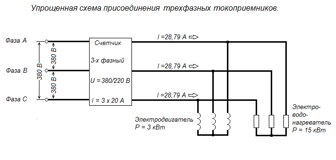
Calculation: We determine the total power of all devices: 3 kW + 15 kW = 18 kW 2. The current flowing in the phase wire at this power is determined by the formula:
![]()
Where: I - current in amperes (A) P - power in kilowatts (kW) U - line voltage, V cos φ - power factor (for household electrical networks, you can take 0.95) Substitute the numbers in the formula: \u003d 28.79 A
Conclusion: The meter will not withstand, so you need to replace it with a current of at least 30 A. For the convenience of users, the current calculation form is given below.
In order not to use the calculator, simply enter your numbers in the form below and click the "Calculate" button.
Form of calculation for determining the current at a three-phase load.
But what about when the three-phase load current is known (the same for each of the phases), which we determined using current clamps or an ammeter, and we need to know the connected power?
Let's convert the formula for calculating current into calculating power.
![]()
In order not to use the calculator, simply enter your numbers in the form below and click the "Calculate" button.
Form of calculation for determining the power at a three-phase load.
Now let's calculate the current at mixed three-phase and single-phase loads.
So, 3 phases are brought into the house and the electrician who installs the electrical wiring should strive to ensure that the phases are loaded evenly, although this is far from always the case.
In our house it turned out, for example, like this: - phase A and a neutral with a voltage between them, as we already know - 220 V brought into the garage and well, as well as courtyard lighting, total load - 12 bulbs of 100 watts, electric pump 0.7 kW or 700 watts. - phase B and neutral with a voltage between them - 220 V are brought into the house, the total load is 1800 watts. - phase C and neutral with a voltage between them - 220 V are brought into the summer kitchen, the total load of the electric stove and lamps is 2.2 kW.
We have single-phase loads: in phase A, the load is 1900 watts, in phase B - 1800 watts, in phase C - 2200 watts, in total for three phases 5.9 kW. In addition, the diagram also shows three-phase loads of 3 kW and 15 kW, which means that the total power of the mixed load will be 23.9 kW.

We enter in turn the values of these powers and calculate the currents.
For phase A it will be - 9.09 A, for B - 8.61 A, for C - 10.53 A. But we already have a three-phase load current flowing through the wires of all three phases, therefore, in order to find out the total value of the current in each of phases, you just need to add the currents of the three-phase and single-phase loads. Phase A 28.79 A + 9.09 A \u003d 37.88 A Phase B 28.79 A + 8.61 \u003d 37.40 A Phase C 28.79 A + 10.53 \u003d 39.32 A. The highest mixed current loads in phase C.
But what if we know the current of a mixed three-phase load (different for each of the phases), which we determined using current clamps or an ammeter, and we need to know the connected power?
In this case, it is necessary to determine the power consumption of each of the three phases in the calculation form for determining the power at a single-phase load and then simply add these powers, which will give us the total power of the mixed three-phase load. Using the mixed load example, we see that the total current in phase A was 37.88 A, phase B was 37.40 A, and phase C was 39.32 A.
7.2. Checking the selected section for voltage loss.
To begin with, according to the known connected power P \u003d 3980 W, phase voltage U f \u003d 220 V and cosine fi 0.95, you need to determine the load current. I will not repeat myself, since we already went through this at the beginning of section 1. "Calculation of the magnitude of an alternating electric current with a single-phase load." In addition, to select the material and wire cross-section, it is necessary to add a safety factor of 30% to the load current or, which is the same, multiply by 1.3. In our case, the load current is 19.04 A. The safety factor of 30% to the load current is 1.3 I n \u003d 1.3 19.04 \u003d 24.76 A.
We select an aluminum wire and, according to table 1.3.5 of the PUE, we determine the nearest largest section, which will be equal to 4 mm 2 for openly laid wires at a current of 32 A.
In order for the user to substitute their own values, the calculation form is given below, consisting of two parts.
Calculation form for determining voltage losses in a two-wire single-phase or two-phase network.
Part 1. We calculate the load current and the current with a safety factor of 30% to select the wire section.
For durable and reliable operation of the electrical wiring, it is necessary to choose the right cable cross-section. To do this, you need to calculate the load in the power grid. When making calculations, it must be remembered that the calculation of the load of one electrical appliance and a group of electrical appliances differ somewhat.
Calculation of the current load for a single consumer
The choice of a circuit breaker and the calculation of the load for a single consumer in a 220 V residential network is quite simple. To do this, we recall the main law of electrical engineering - Ohm's law. After that, having set the power of the electrical appliance (indicated in the passport for the electrical appliance) and given the voltage (for household single-phase networks 220 V), we calculate the current consumed by the electrical appliance.
For example, a household electrical appliance has a supply voltage of 220 V and a nameplate power of 3 kW. We apply Ohm's law and get I nom \u003d P nom / U nom \u003d 3000 W / 220 V \u003d 13.6 A. Accordingly, to protect this consumer of electrical energy, it is necessary to install a circuit breaker with a rated current of 14 A. Since there are none, it is selected the nearest larger one, that is, with a rated current of 16 A.
Calculation of current load for groups of consumers
Since the power supply of electricity consumers can be carried out not only individually, but also in groups, the issue of calculating the load of a group of consumers becomes relevant, since they will be connected to one circuit breaker.
To calculate a group of consumers, the demand coefficient K s is introduced. It determines the probability of simultaneous connection of all consumers of the group for a long time.
The value of K c = 1 corresponds to the simultaneous connection of all electrical appliances of the group. Naturally, the inclusion of all consumers of electricity in an apartment at the same time is extremely rare, I would say incredible. There are whole methods for calculating demand coefficients for enterprises, houses, entrances, workshops, and so on. The demand factor of an apartment will vary for different rooms, consumers, and will also largely depend on the lifestyle of residents.
Therefore, the calculation for a group of consumers will look somewhat more complicated, since this coefficient must be taken into account.
The table below shows the demand factors for electrical appliances in a small apartment:

The demand coefficient will be equal to the ratio of the reduced power to the total K from the apartment = 2843/8770 = 0.32.
We calculate the load current I nom \u003d 2843 W / 220 V \u003d 12.92 A. We select an automatic machine for 16A.
Using the above formulas, we calculated the operating current of the network. Now you need to select the cable section for each consumer or consumer groups.
PUE (rules for electrical installations) regulates the cable cross-section for various currents, voltages, powers. Below is a table from which, according to the estimated power of the network and current, the cable section for electrical installations with a voltage of 220 V and 380 V is selected:

The table shows only the cross sections of copper wires. This is due to the fact that aluminum wiring is not laid in modern residential buildings.
Also below is a table with the range of capacities of household electrical appliances for calculation in networks of residential premises (from the standards for determining the design loads of buildings, apartments, private houses, microdistricts).

Typical cable size selection
In accordance with the cable section, circuit breakers are used. Most often, the classic version of the wire section is used:
- For lighting circuits with a cross section of 1.5 mm 2;
- For circuits of sockets with a section of 2.5 mm 2;
- For electric stoves, air conditioners, water heaters - 4 mm 2;
A 10 mm 2 cable is used to enter the power supply into the apartment, although in most cases 6 mm 2 is enough. But a section of 10 mm 2 is chosen with a margin, so to speak, with the expectation of a larger number of electrical appliances. Also, a common RCD with a trip current of 300 mA is installed at the input - its purpose is fire, since the trip current is too high to protect a person or animal.
To protect people and animals, RCDs with a tripping current of 10 mA or 30 mA are used directly in potentially unsafe rooms, such as a kitchen, bath, and sometimes room outlet groups. The lighting network, as a rule, is not supplied with an RCD.
 (1 ratings, on average: 5,00 out of 5)